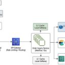
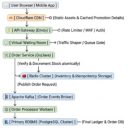
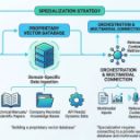
Core Architectural PlacementWhen drawing a Redis caching infrastructure, you must place Redis strategically between your application tier and your persistent database tier. The architecture is typically represented in a three-tier model: 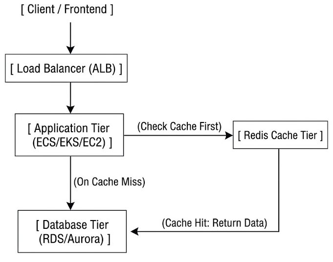
- Application Tier: Acts as the controller. It decides whether to query the cache or the database.
- Cache Tier (Redis): Positioned in-memory for sub-millisecond read/write latencies.
- Database Tier (RDBMS/NoSQL): The ultimate source of truth, used when cache misses occur.
Caching Data Flow PatternsYour diagram should visually demonstrate how data flows. You must choose and illustrate one of the following primary patterns: 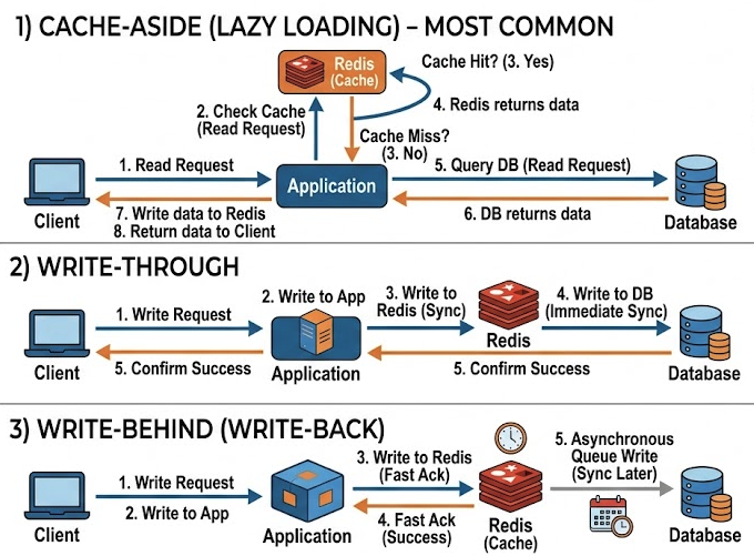
1) Cache-Aside (Lazy Loading) - Most Common- Application receives a read request.
- Application checks Redis (Cache Hit vs. Cache Miss).
- If Cache Hit: Redis returns data to the Application.
- If Cache Miss: Application queries the Database, writes the retrieved data to Redis for future requests, and returns it to the client.
2) Write-Through- Application receives a write request.
- Application writes to Redis.
- Redis (or a helper sync utility) immediately writes to the Database.
- Application confirms success.
3) Write-Behind (Write-Back)- Application writes directly to Redis (fast acknowledgement).
- Redis asynchronously queues the write to be synced to the Database at a later time.
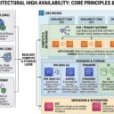
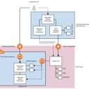
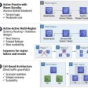
High Availability (HA) & Scaling TopologiesIn enterprise production environments, a single Redis instance is a Single Point of Failure (SPOF). You should draw your Redis layer using one of these two scalable designs: Option A: Redis Sentinel (HA via Replication)Use this when data volume fits within one node, but you require automatic failover. - Master Node: Handles all write operations and replicates data asynchronously to replicas.
- Replica Nodes: Handle read traffic (Read Scalability).
- Sentinel Nodes: Monitor the Master/Replica nodes and trigger automatic failover if the Master goes down.
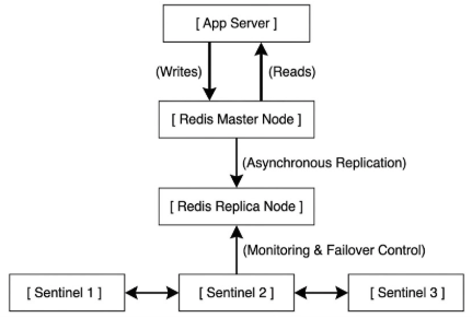
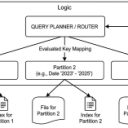
Option B: Redis Cluster (Horizontal Sharding)Use this when your data size exceeds the memory capacity of a single node. - Data is automatically sharded across multiple Master nodes using hash slots.
- Each Master has at least one Replica for HA.
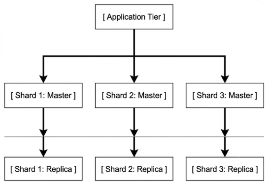
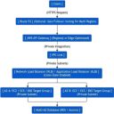
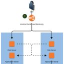
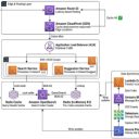
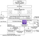
Cloud Infrastructure & Security LayoutWhen drawing the cloud infrastructure (e.g., AWS), place Redis within secure network boundaries: - Virtual Private Cloud (VPC): Encapsulates the entire backend.
- Public Subnet: Contains the Load Balancer (ALB) and NAT Gateways.
- Private Subnet (App): Contains application instances (ECS/EKS).
- Private Subnet (Data): Contains isolated Redis (e.g., AWS ElastiCache) and Databases (RDS).
- Security Groups:
- Allow ingress traffic to Redis (Port
6379) only from the Application Security Group. - Deny all public internet access to Redis.
- Multi-AZ Deployment: Distribute Redis master and replica nodes across different Availability Zones (AZ-A, AZ-B) for disaster recovery.
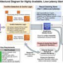
5. Critical Edge-Case Checklist for DiagramsAn expert-level infra design diagram should include annotations or visual callouts addressing these critical caching challenges: - Eviction Policy: Note the policy used when memory is full (e.g.,
allkeys-lru or volatile-lru). - TTL (Time-To-Live): Indicate that cached data has an expiration limit to prevent stale data.
- Cache Penetration Prevention: Note the use of Bloom Filters or caching null values for non-existent database queries.
- Cache Stampede Mitigation: Note the implementation of mutual exclusion (mutex locks) or background pre-calculations to prevent multiple application servers from querying the DB simultaneously when a key expires.
|